
The Skyscraper Museum is devoted to the study of high-rise building, past, present, and future. The Museum explores tall buildings as objects of design, products of technology, sites of construction, investments in real estate, and places of work and residence. This site will look better in a browser that supports web standards, but it is accessible to any browser or Internet device.
FRAME-BRACED CAGE
HAVEMEYER BUILDING
 Installation View
Between the pure masonry bearing wall, used in New York tall buildings well into the 1880s, and steel skeleton construction, which was nearly ubiquitous by 1900, many architects and engineers used a hybrid system: metal cage construction, which employed a complete interior metal frame surrounded by a masonry bearing wall.
Built in 1891, the Havemeyer Building was an imposing edifice a block west of Broadway between Bowling Green and City Hall Park, occupying a long, narrow site that fronted Church Street. Its architect was George B. Post, a leading designer of major high-rises, including in 1890 the World Building for Joseph Pulitzer, which at 309 feet height became the city’s and the world’s tallest office building, as well as the tallest cage-frame building ever constructed. Post favored cage construction as a structural system in part because of the inherent advantages of masonry for fireproofing and to protect against moisture. In addition, though, before a revision in 1892, the New York City building code did not allow for full steel-skeleton construction.
 Installation View
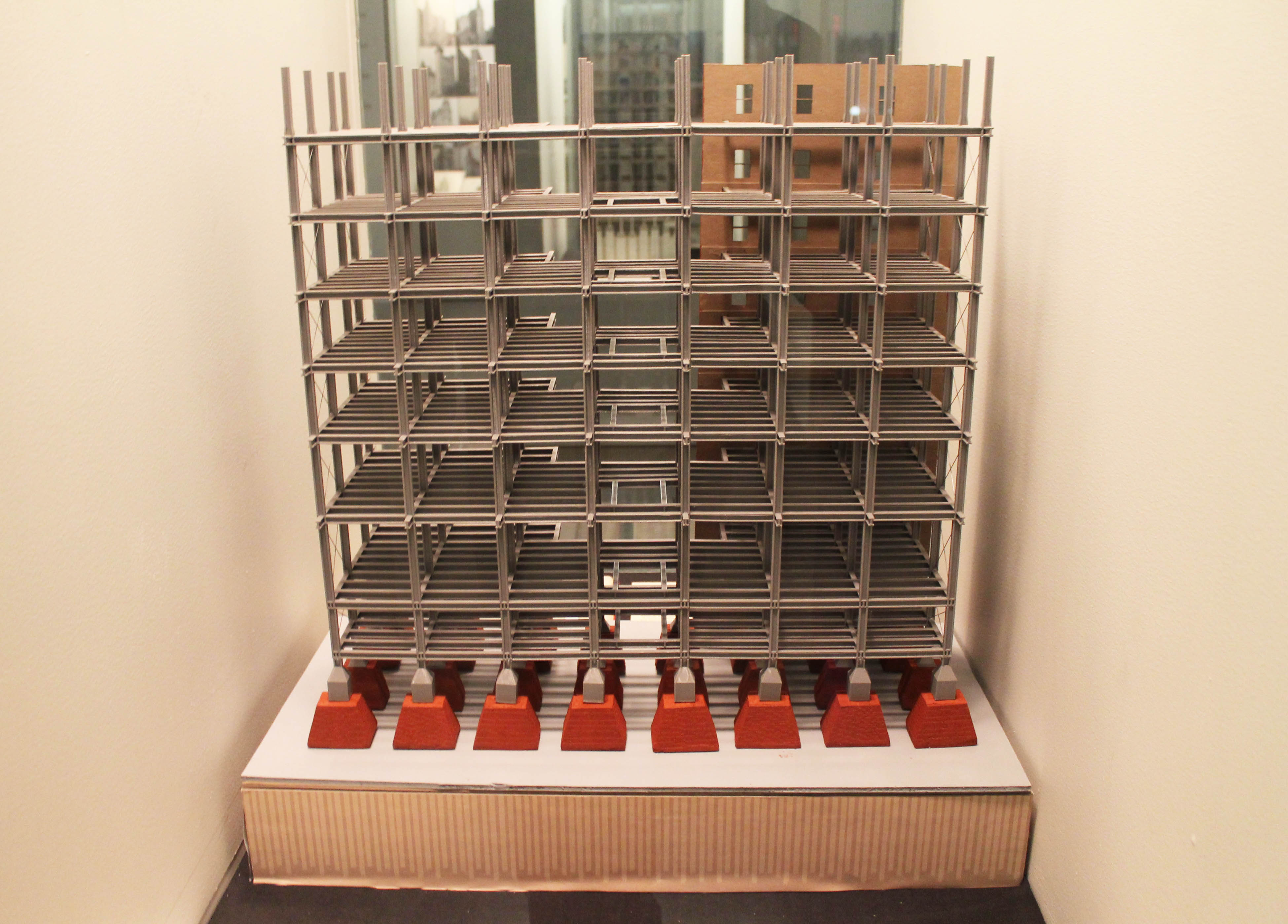
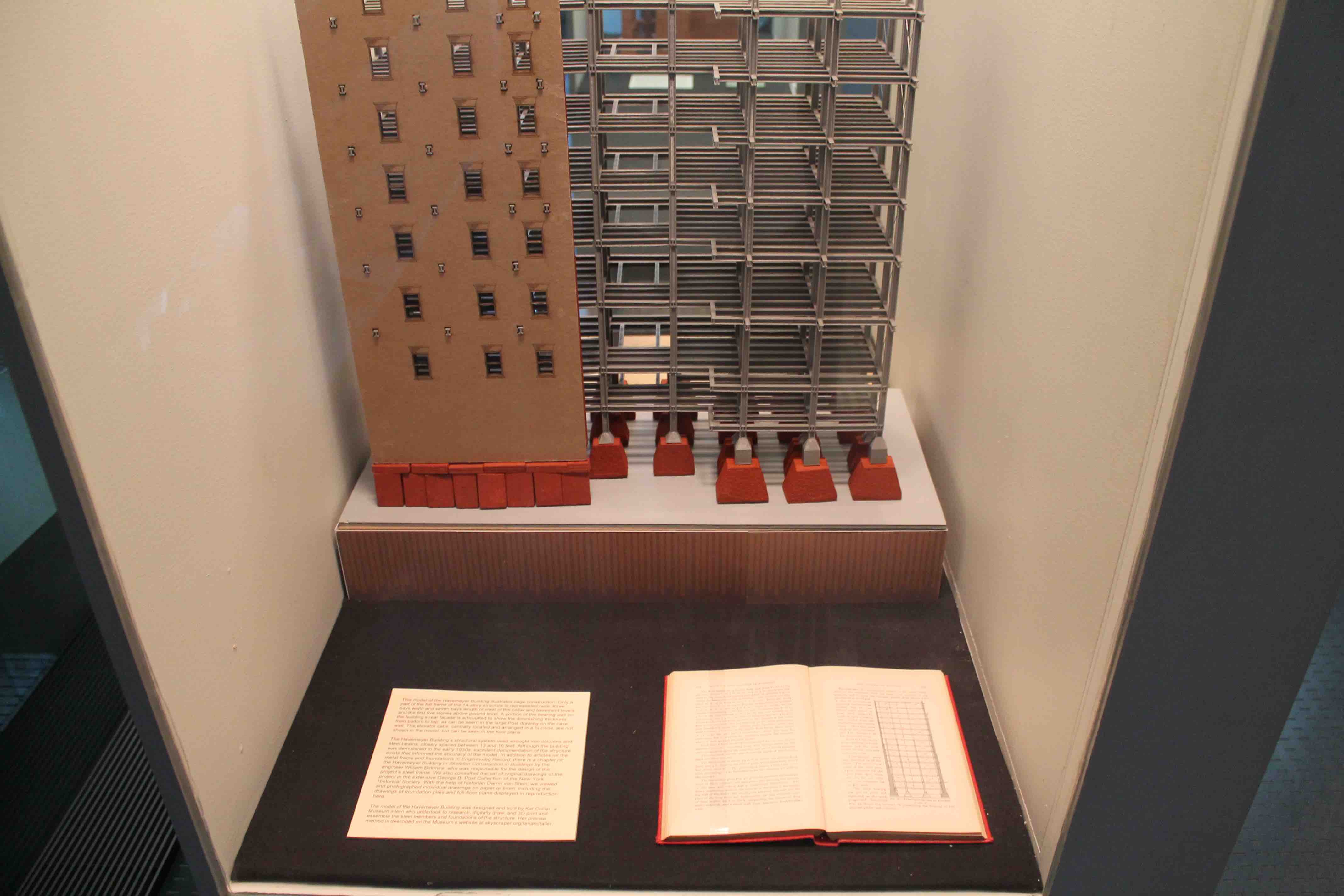
This model of the Havemeyer Building illustrates hybrid steel cage construction. Only a part of the full frame of the 14-story structure is represented here: three bays width and seven bays length of steel of the cellar and basement levels and the first five stories above ground level. A portion of the bearing wall on the building’s rear façade is articulated to show the diminishing thickness from bottom to top, as can be seem in the large Post drawing below. The elevator cabs, centrally located and arranged in a ¾ circle, are not shown in the model, but can be seen in the floor plan.
The Havemeyer Building’s structural system used wrought iron columns and steel beams, which are rather closely spaced between 13 and 16 feet. Although the building was demolished in the early 1930s, excellent documentation of the structure exists that informed the accuracy of the model. In addition to articles on the metal frame and foundations in Engineering Record, there is a chapter on the Havemeyer Building in Skeleton Construction in Buildings by the engineer William Birkmire, who was responsible for the design of the project’s steel frame. Further, we consulted the set of original drawings of the project in the extensive George B. Post Collection of the New-York Historical Society. With the help of historian Darrin von Stein, we viewed and photographed individual drawings on paper or linen, including the drawings of foundation piles and full-floor plans displayed in reproduction here.
The model of the Havemeyer Building was designed and built by Kat Collier, a Museum intern who undertook to research, digitally draw, and 3D print and assemble the steel members and foundations of the structure. Her precise method is described here.
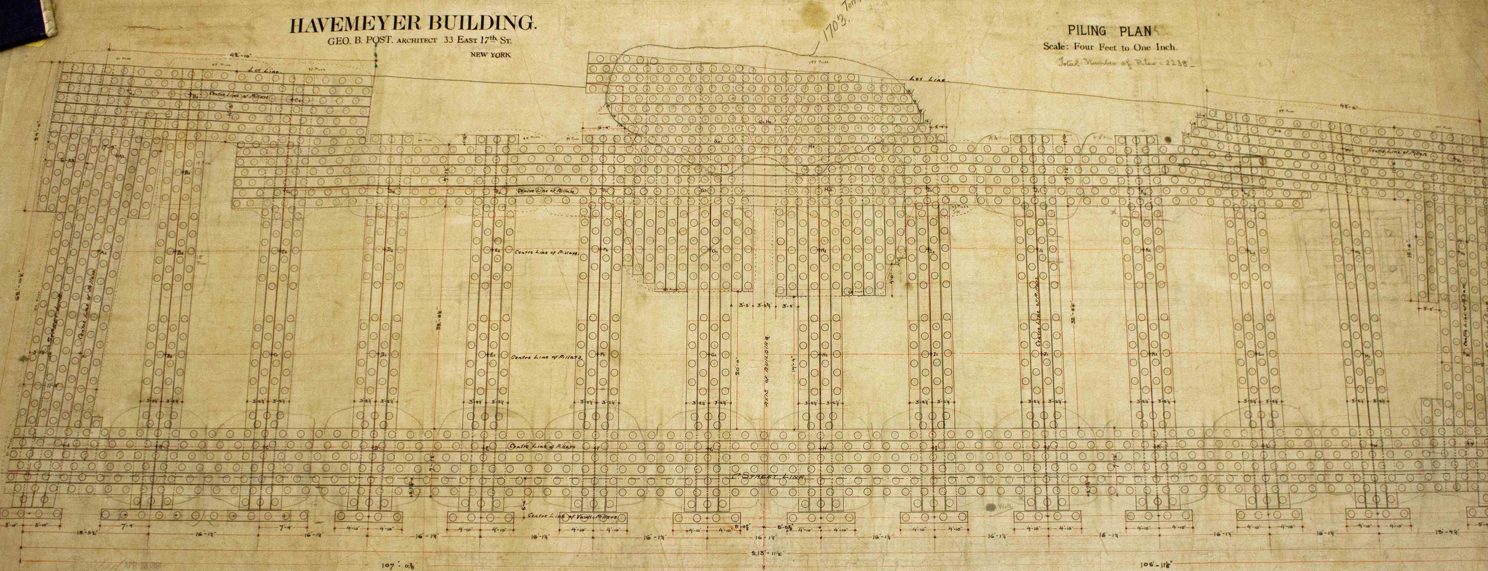 Havemeyer Building, Piling Plan
Dey, Church and Cortlandt Street, 1891-93
Developer Theodore Havemeyer
Architect Geo. B. Post
Photograph of ink on linen drawing, c. 1890-91
George B. Post Collection of the New-York Historical Society
Like many nineteenth-century high-rises, the Havemeyer Building foundations did not rest on bedrock, but was supported on a bed of piles. The piling plan, with its closely-spaced circles, shows the placement of the spruce piles—whole tree trunks stripped of their branches – that served to stabilize the wet sandy soil beneath the building and spread the weight of the heavy metal frame and masonry piers.
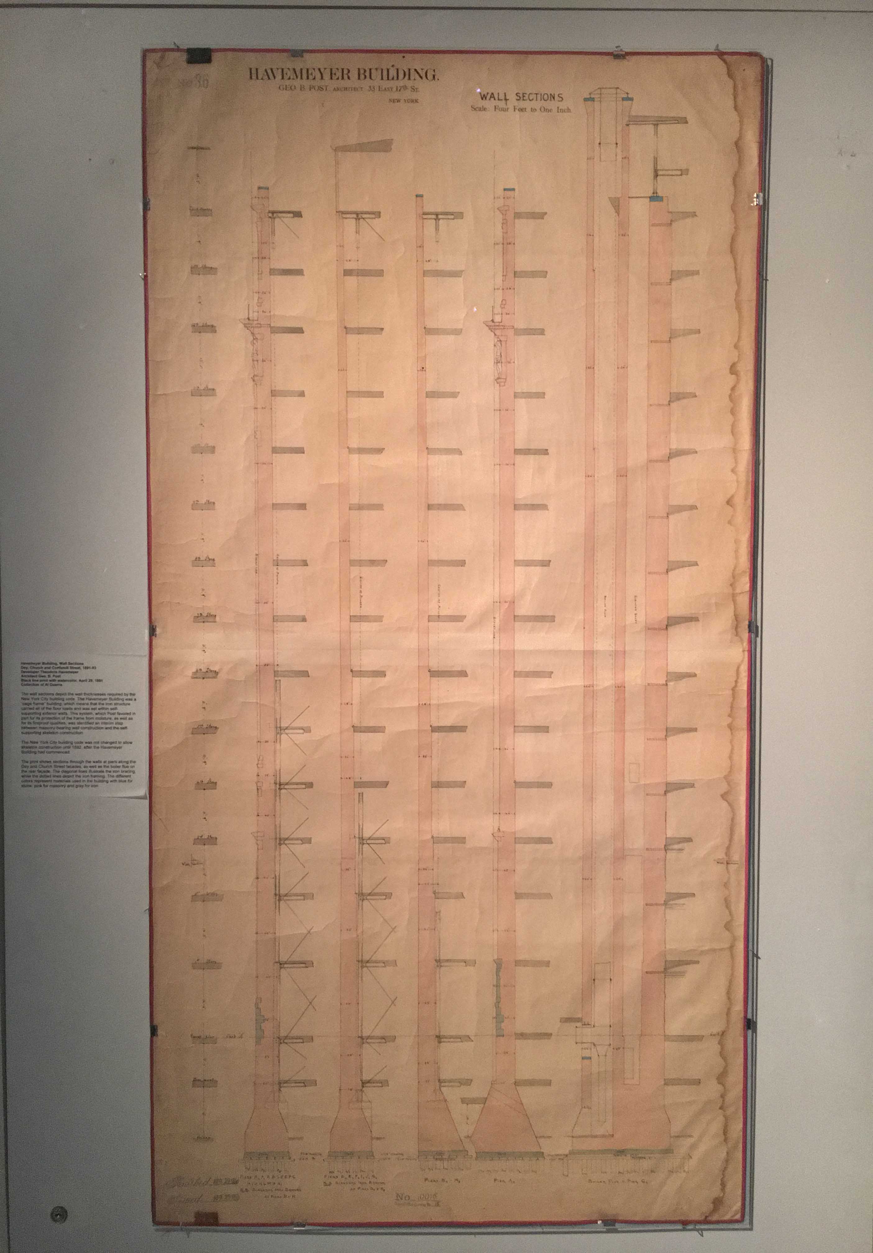
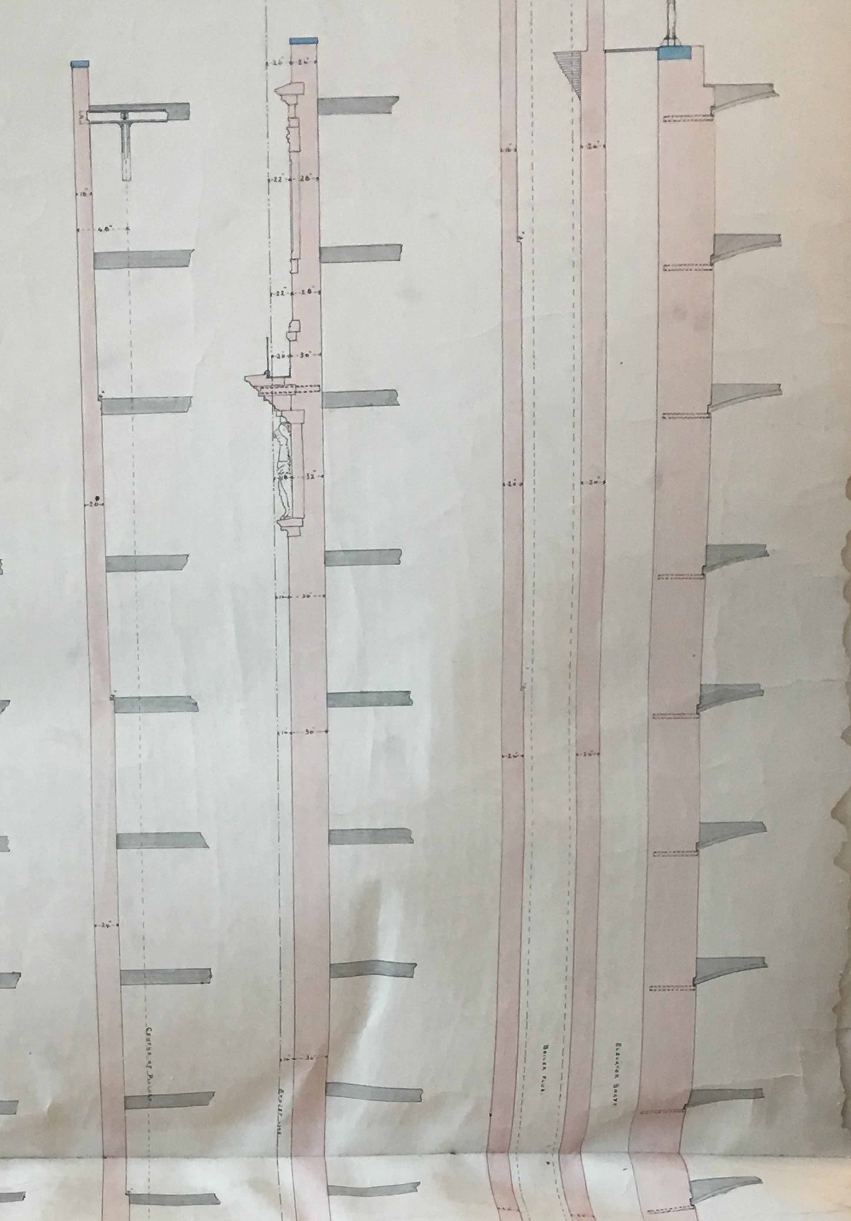 Havemeyer Building, Wall Sections
Dey, Church and Cortlandt Street, 1891-93
Developer Theodore Havemeyer
Architect Geo. B. Post
Black line print with watercolor, April 29, 1891
Collection of Al Guerra
The wall sections depict the wall thicknesses required by the New York City building code. The Havemeyer Building was a “cage frame” building, which means that the iron structure carried all of the floor loads and was set within self-supporting exterior walls. This system, which Post favored in part for its protection of the frame from moisture, as well as for its fireproof qualities, was identified an interim step between masonry-bearing wall construction and the self-supporting skeleton construction.
The New York City building code was not changed to allow skeleton construction until 1892, after the Havemeyer Building had commenced.
The print shows sections through the walls at piers along the Dey and Church Street facades, as well as the boiler flue on the rear façade. The diagonal lines illustrate the iron bracing, while the dotted lines depict the iron framing. The different colors represent materials used in the building with blue for stone, pink for masonry and gray for iron.
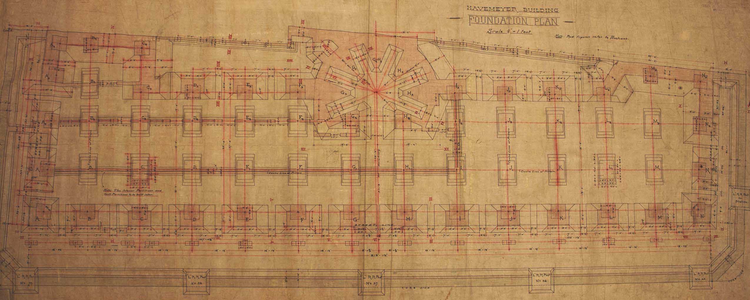 Havemeyer Building, Foundation Plan Detail
Dey, Church and Cortlandt Streets, 1891-1893
Developer Theodore Havemeyer
Architect Geo. B. Post
Photograph of ink on linen drawing, c. 1890-91
George B. Post Collection of the New-York Historical Society
The detailed foundation plan depicts the lowest level of the building and shows the hydraulic equipment that powered the semicircular bank of elevators at the center of the rear wall of the building.
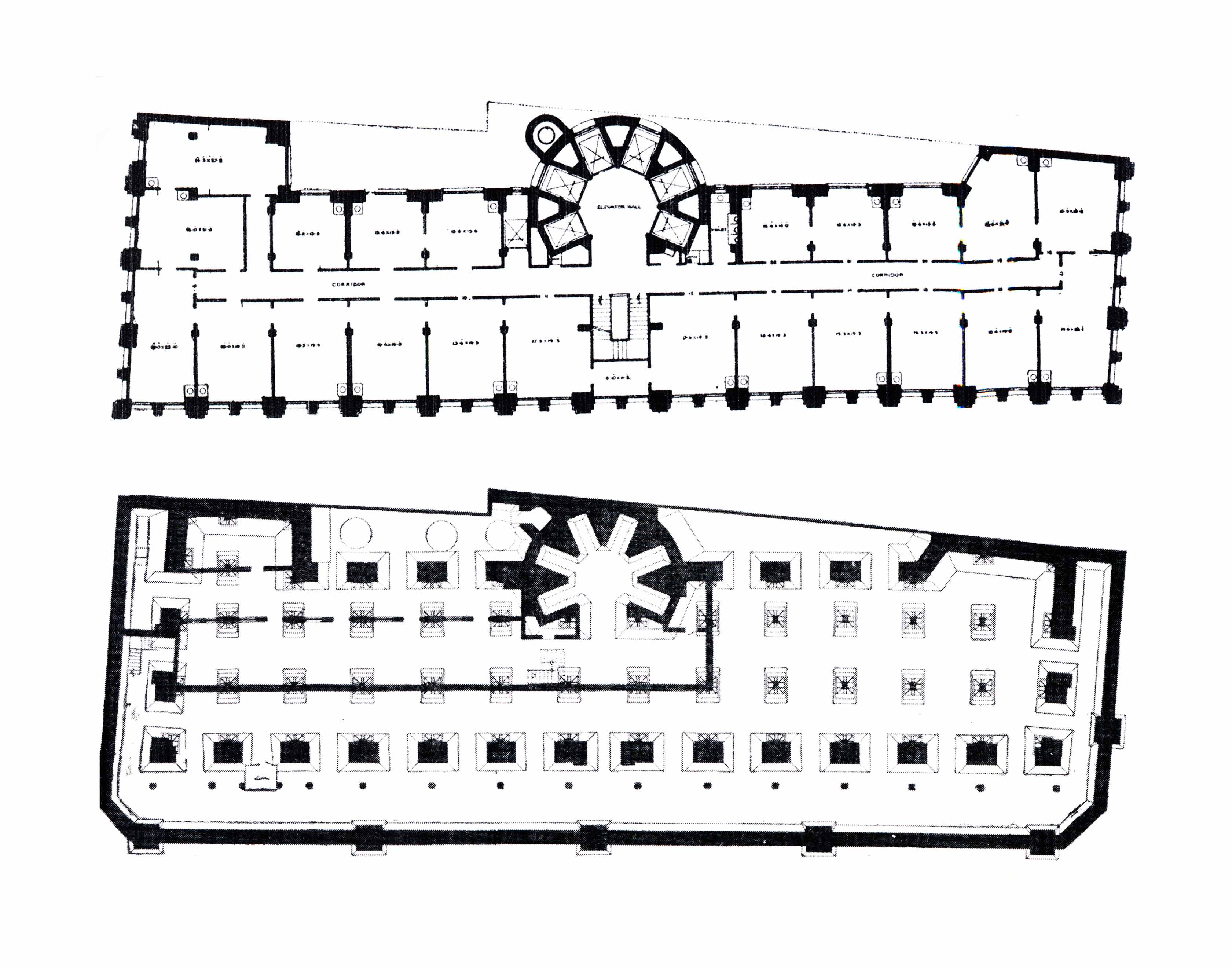 Havemeyer Building, Typical Floor Plan and Foundation Plan
Dey, Church and Cortlandt Streets, 1891-1893
Developer Theodore Havemeyer
Architect Geo. B. Post
William H. Birkmire, Skeleton Construction in Buildings (New York: John Wiley & Sons, 1893)
The Havemeyer Building had a narrow footprint of 47' along Dey and Cortlandt Streets and 214' on Church Street. Due to this and the need for offices to be illuminated by daylight the office floors consisted of a single central corridor with offices to each side and a centrally-located bank of elevators, stairhall, and restrooms. The floor plate of the foundations, which extending under the sidewalk and into the rear of the lot, was much larger than the office floors in order to accommodate the massive foundations and mechanical equipment.
The typical floor plan illustrates the layout of offices with the centrally located bank of seven elevators, stair hall and restroom. The foundation plan shows the structural columns, wall piers—with solid black centers--and continuous street retaining wall. The small black circles in between the Church Street wall piers and retaining wall indicate the piers supporting the basement floor underneath the Church Street sidewalk.
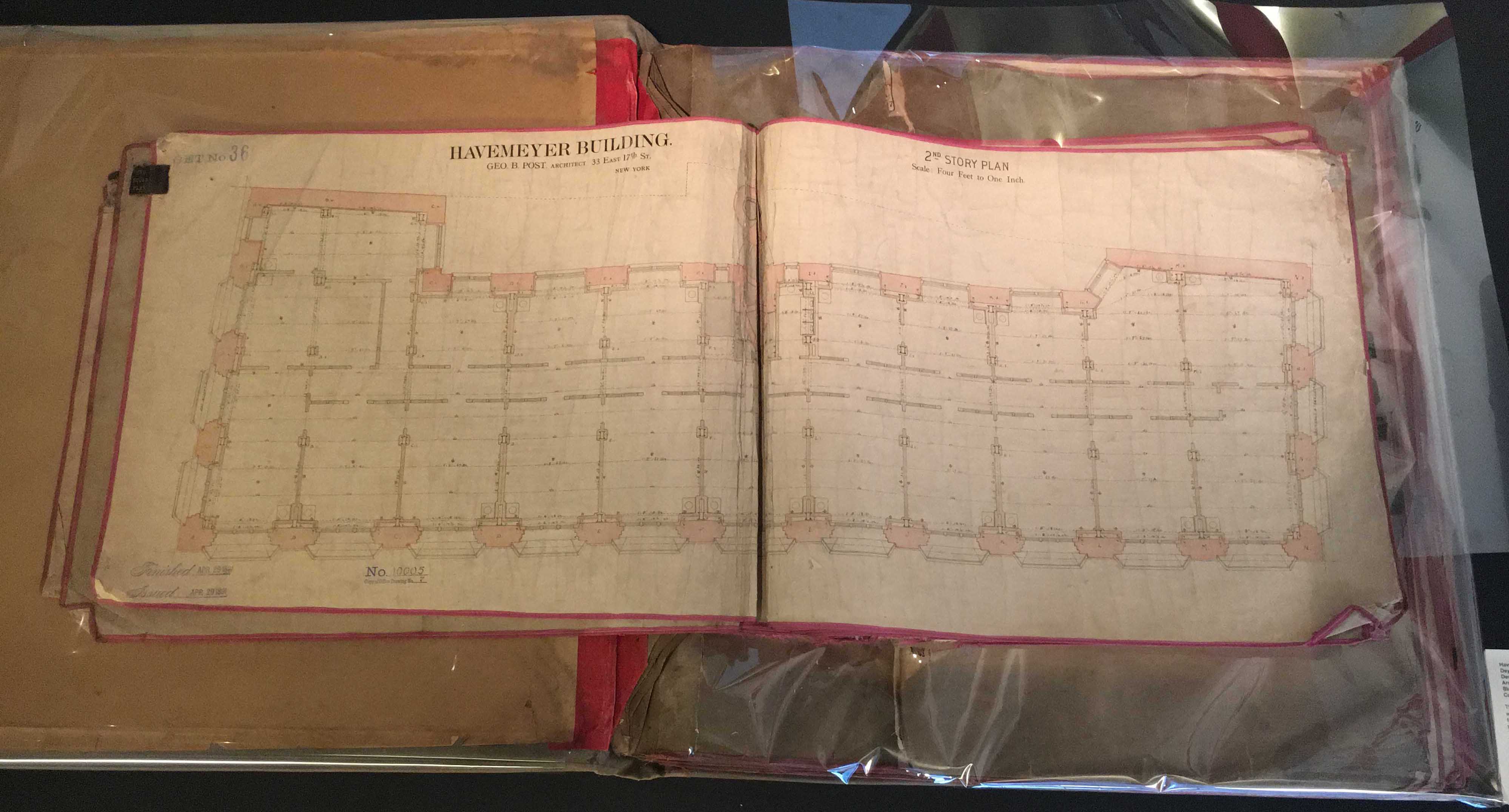 Havemeyer Building, Second Story Plan
Dey, Church and Cortlandt Street, 1891-93
Developer Theodore Havemeyer
Architect Geo. B. Post
Black line print with watercolor, April 29, 1891
Collection of Al Guerra
This folio of floor plans and other prints of architectural drawings was used by either the renting office or the building manager. The folio carries a front label with the name W. B. Duncan, the building’s rental manager and brother-in-law of the developer Theodore Havemeyer, a millionaire of the powerful sugar-refining family. The folio is opened to the Second Story Plan, which illustrates the layout of offices and indicates the large window openings that provide abundant daylight to the offices and thick masonry piers, as well as the location of the structural iron columns.
Three plates of the original folio were extracted by a paper conservator, humidified, and repaired for display on the gallery walls. Photos showing these can be seen below.
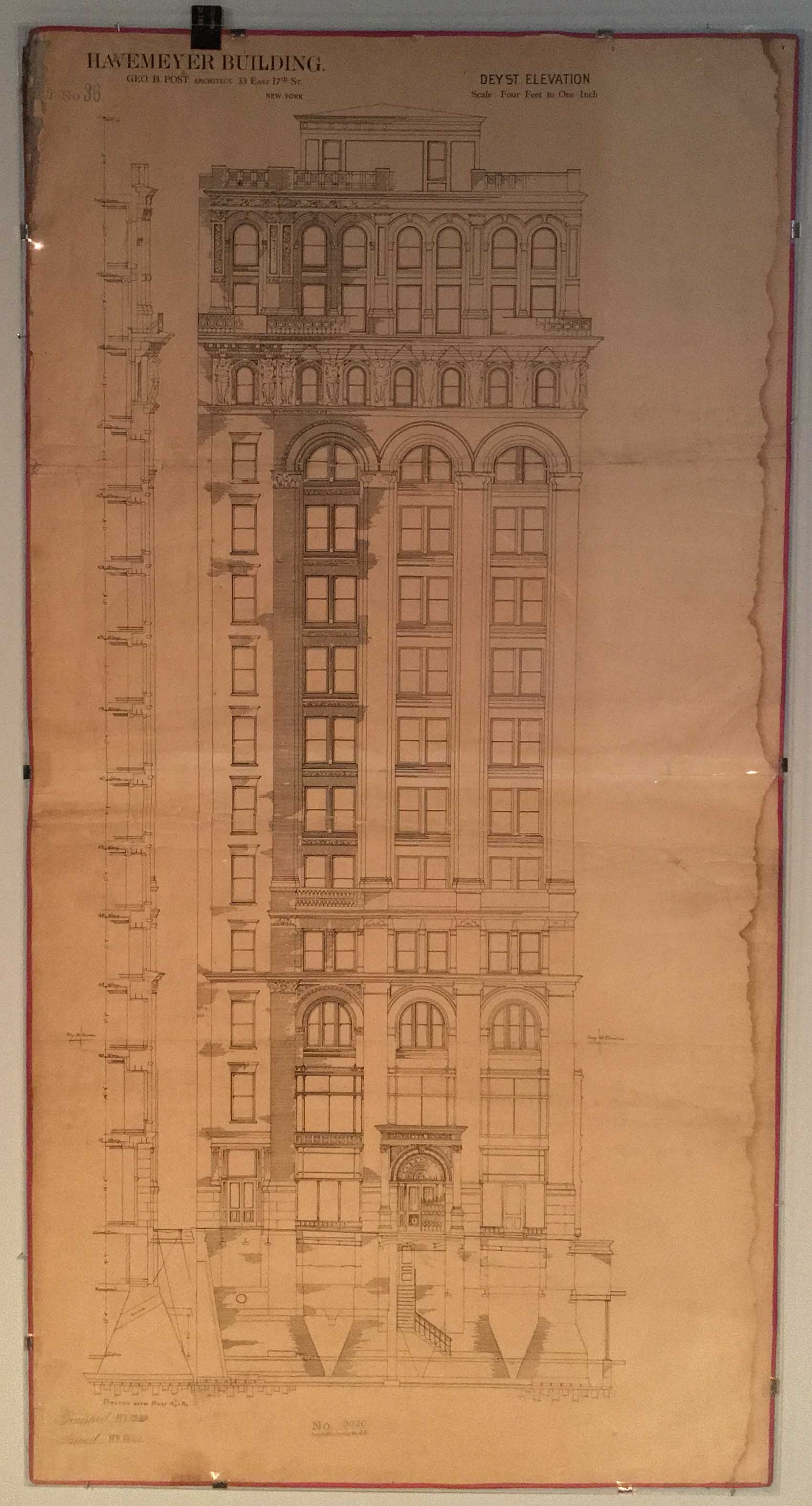 Havemeyer Building, Dey Street Elevation.
Dey, Church and Cortlandt Streets, 1891-93.
Developer Theodore Havemeyer
Architect Geo. B. Post
Black line print, April 29, 1891, Collection of Al Guerra
The 15-story Havemeyer Building occupied the entire blockfront of Church Street between Dey and Cortlandt Streets. The elevated, which ran along Church Street, obscured that façade. The building was light-colored and had brick facades with limestone and terra-cotta trim. The highly three-dimensional structure featured deeply recessed windows and sculptural terra-cotta male atalantes supporting heavy classical cornices.
The Havemeyer Building had two primary facades on Dey and Church Streets. This print shows the Dey Street façade, including a section through the basement and cellar below the sidewalk, from the cellar through the Deck House (15th story) and a section through the Dey Street façade into the first bay of the interior.
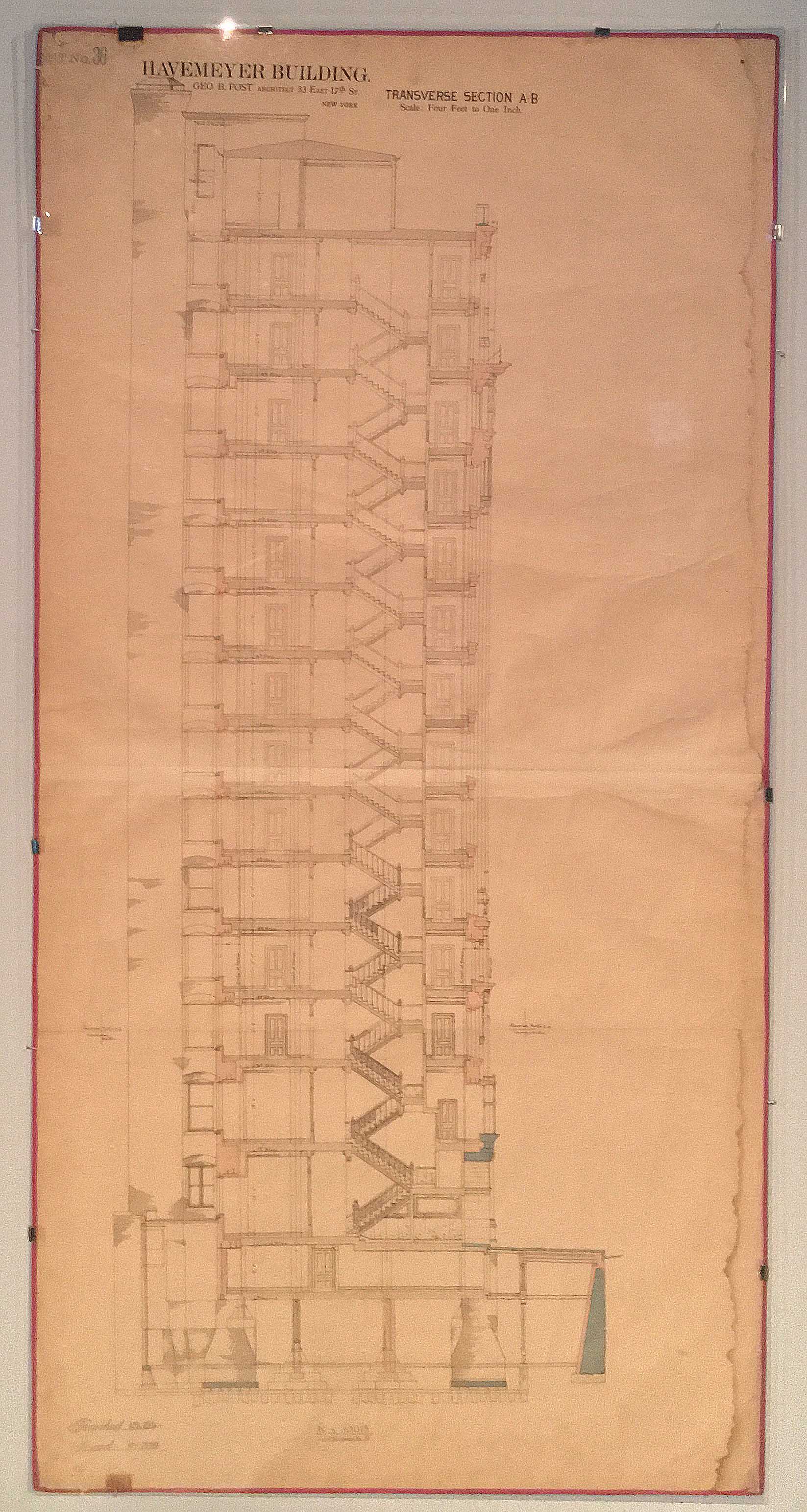 Havemeyer Building, Transverse Section A-B
Black line print with watercolor, April 29, 1891, Collection of Al Guerra
Havemeyer Building, Transverse Section A-B
Black line print with watercolor, April 29, 1891, Collection of Al Guerra
The section illustrates the narrowness of the building due to both the relatively shallow site and the need to illuminate the interiors with daylight as well as the thickness of the masonry walls. The building featured state-of-the art utilities and appointments in order to attract well-paying tenants.
The print shows a section through the building from the Church Street façade to the rear including pilings and foundations. The different colors represent the materials used in the building, with blue for stone, pink for masonry and gray for iron.
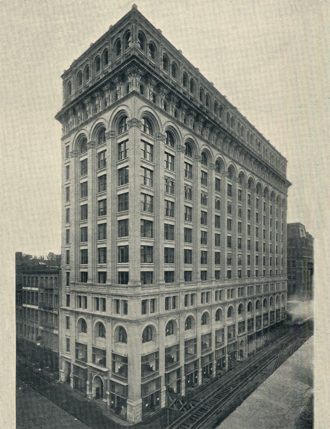 Havemeyer Building, Photographic Plate
Dey, Church and Cortlandt Street, 1895
Developer Theodore Havemeyer
Architect Geo. B. Post
Photograph, c. 1895, King’s Views
A plate from King’s Views 1895 featured here shows the Havemeyer Building looking down Church Street and reveals the immense detail of the façade as well as the sheer breadth of the building.
Model Building Process:
This model of the Havemeyer building used the technologies of 3D modeling, 3D printing, laser cutting and CNC milling. In order to construct this model with the correct dimensions, we used the source Skeleton Construction by William Burkmire and learned the measurements of the foundation work, beam plan, bearing wall thickness and wind bracing. We minimized these numbers down to a 1:64 scale and began the process of building with a digital drawing of the model’s beam plan. Once the digital drawing was finished, we 3D printed it using 1.75mm PLA filament on a Replicator 2, which uses the additive manufacturing process of Fused Deposition Modeling. In order to construct the foundation, we CNC milled expanded urethane and used epoxy to bind to the bottom of the 3D printed steel cage. The bearing wall is constructed out of 8 pieces of 1/16” thick chipboard, of which we layered and laser cut appropriately to represent the thickness of the wall diminishing as the building gets taller. The representative bearing wall connects with the 3D printed steel cage where the beams actually go inside of laser cut i beam holes, becoming apart of the masonry and acting as a hybrid steel cage skeleton.